


Your cart is currently empty!


Art.nr: dah133246
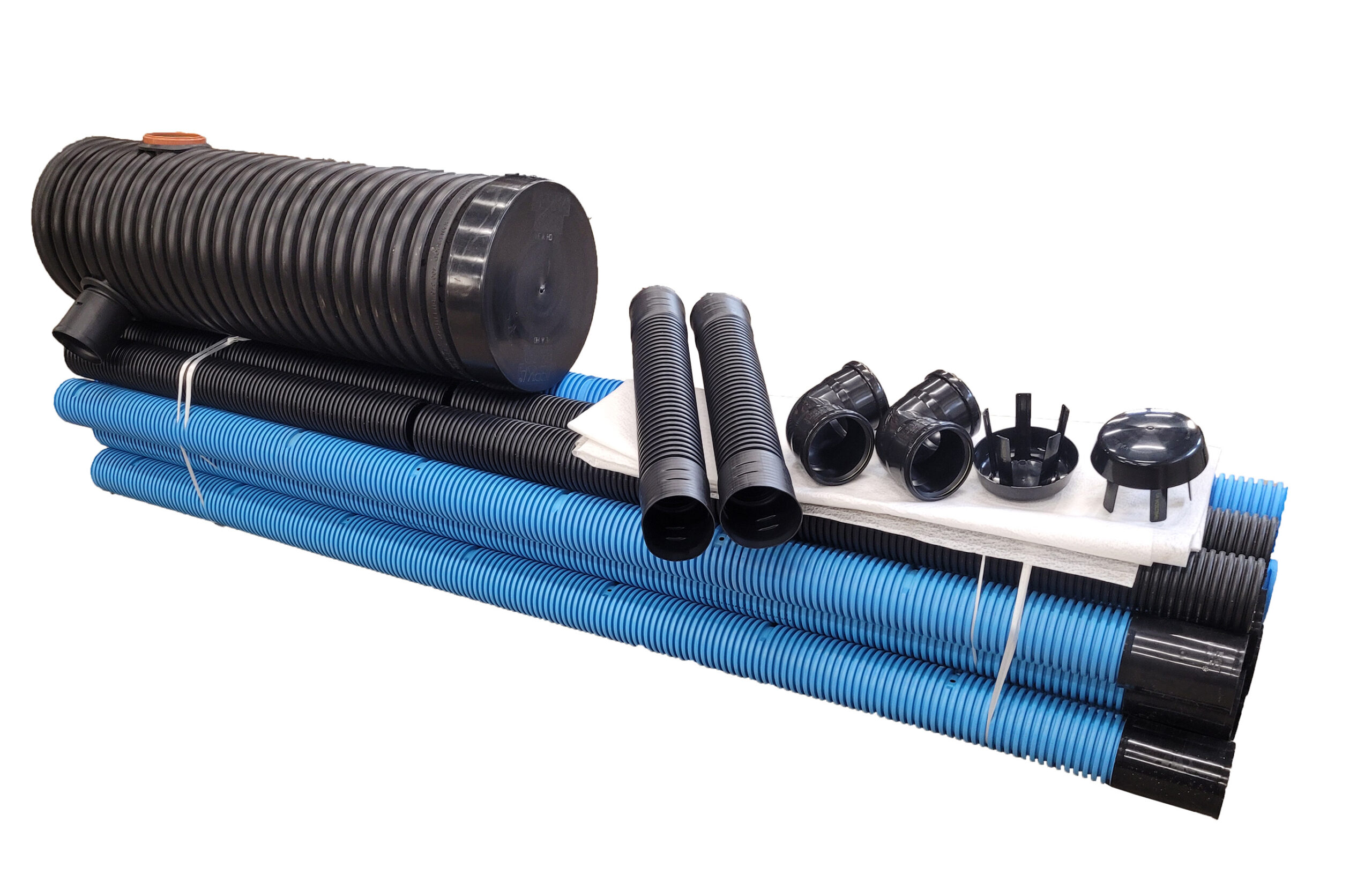
Infiltration package 20m2 (2 strings)
Select the option shipping or pickup Västerås at checkout.
349,14 €
Infiltration bed 20m2 with 2 strings.
To find out the permeability of the soil (LTAR), you can do a percolation test.
With the help of the LTAR value, you know whether it is best to use infiltration or a soil bed.
A test pit should always be dug at the intended area of the infiltration bed, partly to be able to take a percolation sample, but also to be able to determine the groundwater level.
If the distance between the groundwater level and the spreader pipe is less than 1 meter, a raised infiltration bed must be made to achieve the protective distance.
The package contains:
1 distribution well 2 outlets
2 distribution pipes 1m
2 ventilation pipes
8 spreader pipes 2.5m
2 flex bends
6 joint sleeves
2 ventilation hoods
1 non-woven fabric
2 ground bends 110×90° 2 sleeves
How to construct an infiltration bed
1. Spreading layer
The spreading layer is an approximately 30-40 cm thick washed macadam layer with a grain size of 8-16 or 16-32 mm.
The bottom of the trench should be level and smooth, but not compacted no trampling and no vehicles.
The trench can be common to several spreader pipes or provided with a separate trench for each pipe.
The separate trenches can be directed in different directions from the distribution well.
2. Spreader pipes
The bottom of the trench is leveled to form a base for the macadam layer.
The spreader pipes are placed in the macadam layer (edge up) so that the fall of the pipes is 0.5-1 cm/m and so that at least 30 cm of macadam is under the pipes at the end. At least 5 cm of macadam (12-24 or 16-32 mm) shall cover the pipes. The total thickness of the macadam layer is 30-40 cm.
Bends are installed at the outlet ends of the pipes and aeration pipes are connected to them, which should reach above the snow cover in winter.
The distance between the spreader pipes in the same direction in separate strings shall be at least 2 m. The distance between the pipes in a common shaft shall be at least 1.5 m. The maximum length of each individual spreader pipe is 15 m.
The pipes are extended with joint sleeves.
Finally, lay non-woven fabric on top of the pipes and the macadam and fill in the shaft.
3. Filtration layer
Under the Spreading layer the filtration sand is placed.
The filtration layer is made of sand with a grain size of 0-8 mm. The thickness of the layer is approximately 85 cm. On top of the filtration layer there is a distribution layer, with spreader pipes, non-woven fabric and filling soil.
4. Collection layer (only for soil beds)
The collection layer is the bottom layer of the soil bed and its task is to collect the treated wastewater, which is then led in collection pipes to the outlet well.
The collection layer uses collection gravel with a grain size of 8-16 mm. The thickness of the collection layer is approximately 30 cm.
5. Collection pipes (only for soil beds)
Collection pipes are drainage pipes with holes around them through which the treated water is drained. The collection pipes are laid in the collection layer with a slope of 0.5-1.0 cm/m.
At the ends of the collection pipes, bends for aeration pipes are placed well above the ground surface. Aeration hoods are fitted to the aeration pipes
6. Outlet well (only for soil bed)
The collection pipes are led to an outlet well that also serves as a sampling well.
Level a bed for the outlet well at the correct level. Place the outlet well vertically and fill sand around the well.
7. Outlet pipe (only for soil bed)
The treated water is led from the collection well through an outlet pipe
(110 mm) to a suitable place in the terrain, e.g. an open ditch.
If the level differences on the plot are not sufficient for self-fall, the treated water must be pumped to the outlet point.
The outlet of the outlet pipe should be equipped with a stone coffin to protect against ice plugs and prevent small animals such as rodents from entering the system.
8. sealed soil bed (only for soil bed)
A sealed soil bed is constructed by placing a rubber sheet around the entire shaft for the soil bed. Rubber sheets prevent wastewater from entering the groundwater.
A rubber sheet is laid along the bottom of the trench.
The rubber sheet is also laid over the ends of the trench. Make sure that the rubber sheet is not damaged when it is laid. The edge must not be turned in over the soil bed, as this will prevent air from reaching the microorganisms in the soil.
9. Pumping
It is very common to have to pump the wastewater. It is easier to pump the water after the sludge separator and this can be done in two ways, with a pump integrated into the sludge separator or in a separate pump well.
It can be good to have a level alarm that warns if the pump is not working properly.
Usually 32-40 mm PEM hose is used from the pump to the distribution well or directly into the spreader pipe.
If possible, install a straight 110 mm pipe with a self-fall 1-2 meters before the distribution well. This will dampen the flow into the well.
The pump should be fitted with a non-return valve to prevent water from flowing backwards when the pump is not in operation. Many starts and stops on a pump are what shorten the ‘life’ of the pump.
Article number:
dah133246
Brand:
Avloppscenter (AC)