


Your cart is currently empty!


Art.nr: dah9107180
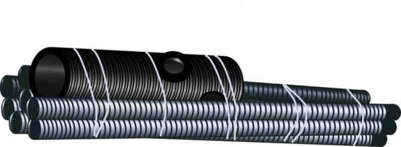
Additional package ground bed 30m2 2 strings
330,74 €
Price pick-up in Västerås, shipping will be added.
Soil bed package of 30m2 to complement an infiltration package.
The package contains:
1st Outlet well
2 m distribution pipe
30 meters Drainage pipe
2pcs bends
2pcs flex bends
4pcs ventilation hoods
4m Ventilation pipe
Soil beds are used in cases where the soil’s absorption capacity is poor, for example due to high groundwater or excessively dense soil layers such as clay, the water must instead be treated in a soil bed and then discharged into the environment.
The soil bed consists of a sand bed where the wastewater is filtered and treated and then discharged.
Infiltration or ground bed – what should I have?
Infiltration bed
Is the most common type of post-treatment stage. The ability of the soil to receive the wastewater determines whether such a facility can be used.
In the infiltration bed, treatment takes place at the bottom of the macadam layer, the sand and in the surrounding soil layers.
An infiltration or soil bed facility can be constructed as a uniform field, in which case the distance between pipes is 1.5 m. Alternatively, they can be constructed as separate trenches with a pipe spacing of approximately 2 m.
Soil bed
In cases where soil absorption capacity is poor,
For example, due to high groundwater, proximity to mountains or excessively dense soil layers such as clay, the water must instead be treated in a soil bed and then discharged into the environment. The soil bed consists of a sand bed where the wastewater is filtered and treated and then drained away and led away.
Sometimes it is necessary to seal the soil bed with a large rubber sheet around all sides except the top.
How to build infiltration and soil bed systems
Described from top to bottom, but of course the installation is built from the bottom up.
1. dispersal storage
The distribution layer is an approximately 30-40 cm thick washed macadam layer with a grain size of 12-24 or 16-32 mm.
The bottom of the shaft shall be level and smooth, but not compacted no trampling and no vehicles.
The trench may be common to several spreader pipes or provided with a separate trench for each pipe. The separate trenches may be directed in different directions from the distribution well.
2. spreader tubes
The bottom of the shaft is leveled to form a base for the macadam layer.
The spreader pipes are placed in the macadam layer (gray edge up) so that the fall of the pipes is 0.5-1 cm/m and so that at least 30 cm of macadam is under the pipes at the end. At least 5 cm of macadam (12-24 or 16-32 mm) shall cover the pipes. The total thickness of the macadam layer is 30-40 cm.
The outlet ends of the pipes are fitted with bends, to which aeration pipes are connected that will reach above the snow cover in winter.
The distance between spreader pipes in the same direction in separate strings shall be at least 2 m. The distance between pipes in a common shaft shall be at least 1,5 m. The maximum length of each individual spreader pipe shall be 15 m. The pipes shall be extended with joint sleeves.
Finally, lay non-woven fabric on the macadam and backfill the shaft.
3. filtration layer
The filtration sand is placed under the spreading layer. The phosphorus is bound to the sand and the organic matter is broken down in the bio layer. The filtration layer is made of sand with a grain size of 0-8 mm. The thickness of the layer is about 85 cm. On top of the filtration layer there is a distribution layer, with spreader pipes, fiber cloth and filling soil.
4. Catchment layer (only for soil beds)
The collection layer is the bottom layer of the soil bed and its task is to collect the treated wastewater, which is then led in collection pipes to the outlet well.
The collection layer uses collection gravel with a grain size of 8-16 mm. The thickness of the collection layer is approximately 30 cm.
5. collecting tube
The collection pipes are drainage pipes with holes all around through which the treated water is led away. The collection pipes are laid in the collection layer with a slope of 0.5-1.0 cm/m.
At the ends of the collection pipes, bends for aeration pipes are placed well above the ground surface. Aeration hoods are fitted to the aeration pipes
6. Discharge well (only in case of soil bed)
The collection pipes are led to an outlet well which also serves as a sampling well.
Level a bed for the outlet well at the correct level. Place the outlet well vertically and fill sand around the well.
7. outlet pipe
The treated water is led from the collection well through an outlet pipe
(110 mm) to a suitable place in the terrain, e.g. an open ditch.
If the level differences on the plot are not sufficient for self-fall, the treated water must be pumped to the outlet point.
The outlet of the discharge pipe should be fitted with a stone coffin to protect against ice plugs and prevent small animals such as rodents from entering the system.
8. dense soil bed
A sealed soil bed is constructed by laying a rubber sheet around the entire shaft for the soil bed. Rubber sheets prevent wastewater from entering the groundwater.
A rubber sheet measuring approximately 15 x 7.5 m is laid out along the bottom of the shaft.
The rubber sheet is also placed over the ends of the shaft. Make sure that the rubber sheet is not damaged when it is laid out. The edge must not be turned in over the soil bed, as this will prevent the air supply to the microorganisms present
in the soil.
9. pumping
It is very common to have to pump the wastewater. It is easier to pump the water after the sludge separator and this can be done in two ways, with a pump integrated into the sludge separator or in a separate pump well.
It can be useful to have a level alarm to warn you if the pump is not working properly.
Usually 32-40 mm PEM hose is used from the pump to the distribution well or directly into the spreader pipe.
If possible, install a straight 110 mm pipe with self-fall 1-2 meters before the distribution well. This will dampen the incoming flow.
Article number:
dah9107180
Brand:
Avloppscenter (AC)